Ferroli Domina C 24 E Manual
вторник 25 декабря admin 62
Ferroli Domina C 24 E Manual Rating: 3,7/5 7423 votes
14 section 5 - installation Instructions 5.1 Boiler Packaging The boilers are supplied in different packagings: Boiler Flue System (separate) Hardware Pack (separate) 5.2 Fitting/Mounting the Boiler Decide where the boiler is to be fixed on the wall, taking into account installation requirements detailed in previous section. Screw the wall mounting plate to the wall choosing one of the two sets of slots in left and right bank. Ensuring that at least one of the screws is fitted into a top slot. Example of fixing 5.4 internal wiring The boiler has been pre-fitted with a 3 amp fused approved moulded 3 pin and flying lead for use with 230V 50Hz. If the supply cord is damaged, it must be replaced by the manufacturer, its service agent or similarly qualified persons in order to avoid a hazard. The plug should be used with an unswitched/shuttered socket outlet complying with BS1363.
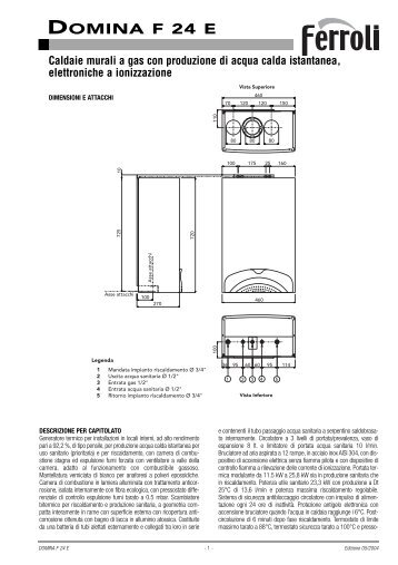
15 Feb 2011 ferroli manual uso caldera domina f 24 e - Manual y Guia del Usuario, Instrucciones, Manual Gratis. Manual del Usuario. DOMINA F 24 E. DOMINA F 24 E. Carlos Javier Hernandez. Connect to download.
The boiler comes pre-fitted with a link wire between the room thermostat/timer connections on the terminal strip. This creates a permanent call for heat and must be removed when adding a room thermostat. 4 Cable Clamp 2. Lift the boiler onto the wall mounting plate, locating it over the two tabs. Room Thermostat - Wiring To fit a room thermostat proceed as follows: 1.
Ensure that the electrical supply to the boiler is isolated before proceeding. Remove the two screws beneath the flap on the front of the boiler and lower the front panel.
Remove the pre-fitted link wire between the Room stat/timer terminals. Pass the cable through a grommet, secure with the cable clamp and connect the room stat as shown in the diagram below. If room stat has a neutral connection, connect this to terminal N (load) in the fused spur. Carry out all necessary electrical checks. Raise the front panel and relocate the two screws under the small flap. Check operation of room stat if possible. If present, remove the bottom end support packaging and ensure all plastic plugs are removed from CH & DHW connections.
5.3 Wiring InstruCTIons WARNING: THIS APPLIANCE MUST BE EARTHED Connections must be made in such a way that allows complete isolation of the electrical supply, e.g. Double pole switch with 3mm contact separating in both poles. L N N Room Stat ROOM STAT/ TIMER 14 15 60 section 5 - installation Instructions 5.5 Water and Gas ConnectionS Ensure all boss blanking plugs are removed before making any connections. Each valve must be fitted to the correct boss as shown in diagram below Do not subject any of the isolating valves to heat as the seals may be damaged. Ensure that the green fibre washer is used on the CH flow connection. IMPORTANT - The gas service cock is sealed with a top hat washer - DO NOT subject to heat. Pressure Relief Valve (PRV) - Located at the bottom right hand side of the boiler connection via a 15mm diameter stub pipe.
0 of 0 people found the following review helpful: 39' Bamaboo Shinai January 18, 2019 Reviewer: NV from Iowa I am new to the art of Kendo and e-bogu was recommended to me. Could not be happier. Will definitely be a returning customer! Excellent quality and incredible customer service. Was this review helpful to you? Shutochnaya biografiya yubilyara v stihah.
Use a replaceable connection to ease the replacement of the valve if required. Ensure a safe discharge point using temperature and pressure resistant materials. 5.6 Air / Flue Systems The flue system is part of the appliance and is approved as such.
Only use the flue systems supplied by Morco. The standard flue kit (RSF303) for the Morco GB range is a 600mm as shown below. There is also a 900mm kit available (RSF305). Turret 100 CH FLOW DHW OUTLET COND. DRAIN GAS INLET DHW INLET CH RETURN PRV Part No. RSF303 The minimum cut length is 138mm (includes 30mm into elbow) The maximum allowable length using extensions (RSF341) is: GB24-8m (minus any flue kit options) GB30-7m (minus any flue kit options) 15 16 section 5 - installation Instructions 5.7 determining THE flue length IMPORTANT.