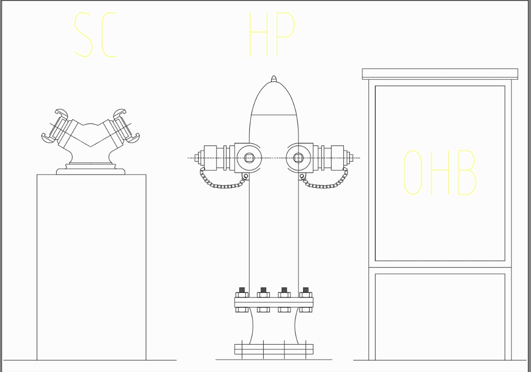
Fire Hydrant Autocad Dwg
пятница 28 декабря admin 18
Fire Hydrant Autocad Dwg Rating: 3,6/5 8395 votes
Apr 25, 2017 Fire Hydrant Fire Hydrant Safety and Security is the state of being “safe” (from French sauf), the condition of being protected from harm or other non-desirable outcomes. Safety can also refer to the control of recognized hazards in order to achieve an acceptable level of risk. Fire Hydrant Safety and Security is the state of being 'safe' (from French sauf), the condition of being protected from harm or other non-desirable outcomes. Free CAD Block Symbols And CAD Drawing Search.
If you do not create an armature, the system creates a fitting at the location where the pipe is attached to the main pipe (feature rule). • In the Industry Model Explorer, click the Workflow explorer icon. • Right-click Fire Hydrant Creation. • Click Execute.
• Specify a reference record, if any. • Under Pipe from Hydrant to Main Pipe, select Straight Pipe or Digitize Pipe. If you choose Straight Pipe you are prompted to select the main pipe in the drawing. The connection is created as an orthogonal projection on the main pipe. • Specify whether to add an armature, or a valve on the main pipe.
• Follow the prompts. • Press ESC to finish the workflow. When you are finished creating geometry, the feature class form is displayed so you can add attribute data. Arcsoft photoimpression 4 downloads.
Last updated Feb. 06, 2019 - 3:15 pm The standard detail drawings below apply to all. They are intended to be used as a guide in the preparation and submittal of plans for private development and city contract projects within the City of Raleigh and the city's extra-territorial jurisdiction. All construction shall conform to either these City of Raleigh specifications or to the latest edition of the NCDOT Standard Specifications for Road and Structures.
If a required detail is not included on this web page, the North Carolina Department of Transportation (NCDOT) Roadway Standard Drawings shall apply. Any questions regarding the NCDOT Standard Drawings should be directed to the NCDOT, Design Services Unit at 919-250-4128. Complete Bicycle Facility Standard Detail Drawings: • • • Individual Bicycle Facility Standard Detail Drawings: Detail Description Format B-10.01 Bike Lane Signs & Markings B-10.02 Bike Lane Buffer Markings B-10.03 Bike Lane Signs & Markings Approaching Intersections B-10.04 Bike Lane Markings through Intersections & Driveways B-10.05 Shared Lane Signs & Markings B-10.06 Bicycle Markings B-10.07 Bicycle Signs B-20.01 Bike Rack Placement B-20.02 Bike Rack Corral B-20.03 Bike Rack Details Contact: Transportation Planning Manager 919-996-2161. Complete Tree Protection and Planting Standard Detail Drawings: • • • Individual Tree Protection and Planting Standard Detail Drawings Detail Description Format TPP-01 Standard Tree Protection TPP-02 Tree Protection Fence Layout TPP-03 Tree Planting TPP-04 Trenching I Tunneling near Existing Trees TPP-05 Pruning Box for Utility Easement TPP-06 Tree Grate in Sidewalk within Row TPP-07 Tree Planting in Sidewalk within Row TPP-08 Standard Temporary (sediment/silt) / Tree Conservation Area Fence Detail TPP-09 Tree Armour Contact: Capital Projects Superintendent 919-996-4115.
